Order number
S11101 / S11101H
Availability
Usually in stock
Accessories
Documents
Description
Classified according to IEC 61400-12-1 Edition 2.0 (2017-03)
The Thies FCA X Anemometer has the best classification values on the market. Its built-in pressure sensor automatically corrects the wind speed measurement depending on air pressure.The new low power version now has an even lower consumption (typ. 14mA at 12V) in IEC classified mode and up to eight sensors can be connected in a single bus.
Since the old version uses the same communication protocol as the new one, they can be used in the same bus.
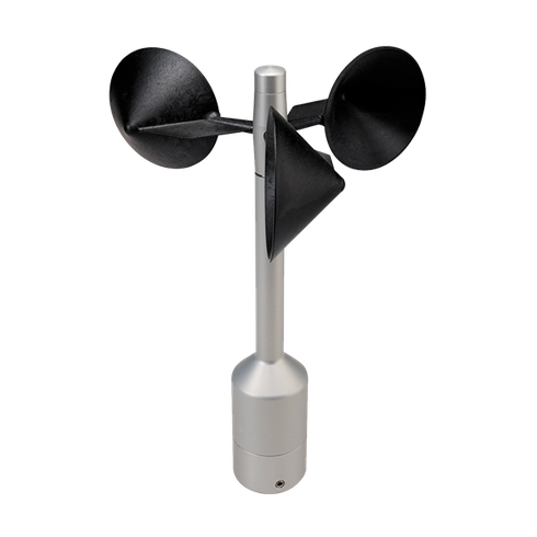
Intelligent optically-scanned cup anemometer
Thies First Class Advanced X is classified acc. to IEC 61400-12-1 Ed. 2.0 (2017-03). It has been designed to measure:
- Horizontal wind speed
- Absolute and relative air pressure
- Inclination X, Y and Z
- Acceleration, frequency and amplitude of vibration measurement in X, Y and Z
The anemometer is designed for measuring of wind resources for assessment reports and power curves. The sensor is characterized by minimal deviation from cosine line, optimized dynamic behavior even at highly intense turbulences, minimal overspeeding, low starting value and optimized oblique inflow behavior. It requires only low maintenance thanks to its low-inertia and ball-bearing cup star. For winter operation the electronically regulated heating guarantees smooth running of the ball bearings and prevents icing of shaft and slot.
Intelligent correction of measurement values
The sensor integrates an automatic correction of the wind speed measurement value depending on air pressure. The revolutions per minute (rpm) of the cup star depend on air density and thus on air pressure. The correction is implemented for 700 … 1100 hPa. The anemometer output covers both original and corrected measurement values.
Calibration
For wind resource assessment, anemometers have to be calibrated acc. to MEASNET. Thies First Class Advanced X can save slope and offset values determined during calibration. Thus no further corrections have to be made. We recommend calibrating anemometers in the wind tunnel of Ammonit Wind Tunnel GmbH (ammonit-windtunnel.com).
Configuration of counter output to be in IEC classified mode
When the anemometer is configured with the parameter FO = 4 then the counter output gives the air pressure corrected wind speed output which obtained the IEC classification result described below.
wind speed [m/s] = 0,1 [m] × f [Hz]
Low power configuration of sensor fulfilling the IEC classified mode (Heating OFF)
Per default we deliver the sensor in a configuration which is at the same time low power and IEC classified (Heating OFF).
If you do not have large power ressources in your measurement campaign (especially offgrid) we recommend you to keep this default configuration. Then both the counter and the serial output give the air pressure corrected wind speed output which obtained the excellent IEC classification result (Heating OFF), but at the same times keeps a low power consumption (typ. 14mA at 12V).
S Classification value for warm climate countries
Please note that if your measurement campaign takes place in a country with a warm climate (no season below 10°C), then the S classification value for this climate matches the IEC classified mode (Heating ON) even if the sensor is configured in low power mode.
High power configuration of sensor to be in IEC classified mode (Heating ON)
If you have large power ressources available in your measurement campaign (up to 20W available per anemometer), and you have climate with cold winter, then please inform us, we will configure the sensor in order that it fulfils the IEC classified mode (heating ON).
Please note that you will need to take the version S11200H (heating version) and a special cable with heating cores.
Classification acc. to IEC 61400-12-1 Edition 2.0 (2017-03)
The direct influence of air density was measured using a specially designed variable air density wind tunnel, instead of calculating the influence of air density by using torque measurements.
| Class A | Class B | |
| Heating ON | 0.65 | 0.9 |
| Heating OFF | 1.1 | 1.8 |
Source: Summary report AK 151023-1.1 Cup Anemometer Classification, Deutsche WindGuard Tunnel Services GmbH, Varel, Germany, 2017.
Operational standard uncertainty acc. to IEC 61400-12-1
The operational standard uncertainty describes the maximum deviation of the wind speed measured by the anemometer
compared with the real wind speed. The table indicates the operational standard uncertainty at 10 m/s:
| Class A | Class B | |
| Heating ON | 0.04 m/s | 0.05 m/s |
| Heating OFF | 0.06 m/s | 0.10 m/s |
Linearity (MEASNET)
The MEASNET required linearity for anemometers is r > 0.999 95. The Thies First Class Advanced II offers r > 0.999 99 (4 … 20m/s).
Specifications
| Characteristics | |
|---|---|
| Physical functionality | Optically-scanned cup anemometer |
| Delivered signal | Frequency output (pulse) and RS485 (Modbus) |
| Accuracy | |
| Accuracy wind speed | ±1% of measured value or < ±0.2m/s @ 0.3 … 50/s |
| Accuracy housing temperature | ±1° (Measurement range: -40 … +80°C) |
| Accuracy air pressure | ±1hPa @ 20°C (Measurement range: 300 … 1100hPa) |
| Accuracy inclination (X, Y, Z) | ±1° (Measurement range: -89.9° … +89.9°) |
| Accuracy vibration (X, Y, Z) | ±0.4Hz (Measurement range: 0 … 50Hz) |
| Accuracy acceleration | ±30 mg (Measurement range: ±8g) |
| Linearity | Correlation factor r between frequency f and wind speed y
r > 0.999 99 (4 … 20m/s) |
| Starting velocity | < 0.3m/s |
| Resolution | 0.05m wind run |
| Distance constant | < 3m (acc. to ASTM D 5096 – 96) 3m acc. to ISO 17713-1 |
| Turbulent flow into cups | Deviation Δv turbulent compared with stationary horizontal flow
-0.5 % < Δv < +2 % Frequency < 2Hz |
| Wind load | Approx. 100 N @ 75m/s |
| Operating range | |
| Measuring range | 0.3 … 75m/s |
| Survival speed | 80 m/s (mind. 30 min) |
| Permissible ambient conditions | -40 … +80°C, 0 … 100% RH including condensation |
| Electrical data | |
| Output signal (frequency) | Form rectangle, 1082 Hz @ 50 m/s, supply voltage max. 15 V |
| Output signal (RS485) | Modbus protocol, bus-compatible
Half duplex, data format: 8N1 Baud rate: 2400, 4800, 9600, 19200, 38400, 57600 |
| Electrical supply for optoelec. scanning | Voltage: 3.7 … 42VDC (galvanic isolation from housing)
Current: typically 14mA, max. 100mA (with heating for pressure sensor on) approx. 0,9mA (power saving mode SM1,HT0) |
| Electrical supply for heating (only S11200H) |
Voltage: 24 V AC/DC (galvanic isolation from housing)
Idling voltage: max. 32VAC, max. 48VDC Power consumption: 25W |
| General | |
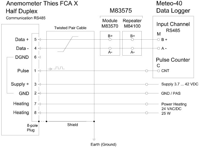
| Connection | 8-pole plug-connection for shielded cable in the shaft |
| Mounting | on mast tube R1” (Outer diameter ≤ 34mm, Inner diameter ≥ 22mm) |
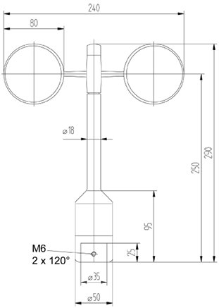
| Dimensions | 290 x 240mm |
| Fixing boring | 35 x 25mm |
| Weight | approx. 0.5kg |
| Material Housing
Cup star |
Anodised aluminiun
Carbon-fibre-reinforced plastic |
| Type of bearings | Metallic ball bearings |
| Protection | IP 55 (DIN 40050) |
| Patent | EP 1 398 637, DE 103 27 632, EP 1 489 427 |
| EMC | EN 61000-6-2, EN 61000-6-3, EN 61010-1, EN 50581 |
| Manufacturer | Thies |
| Accessory | Module set M83575 (incl. isolated repeater) |
Dimensional drawing
Sensor connection diagram
Instructions